Well now, for once one of the APC site adds actually had something relevant that I could relate to for once... Sadly for them I saw their add too late for it to matter... bawhahahahaha
![Image]()
My water change setup is relatively easy to make. The basic design involves three parts: an overflow, a fresh water source, and safety features to prevent overflowing. This water change system is continuous (meaning it runs 24 hours a day at a very slow rate). I have well water with no chlorine, or added softening salts. My tanks are conveniently placed in the basement where this water change system is set up.
Overflow System:
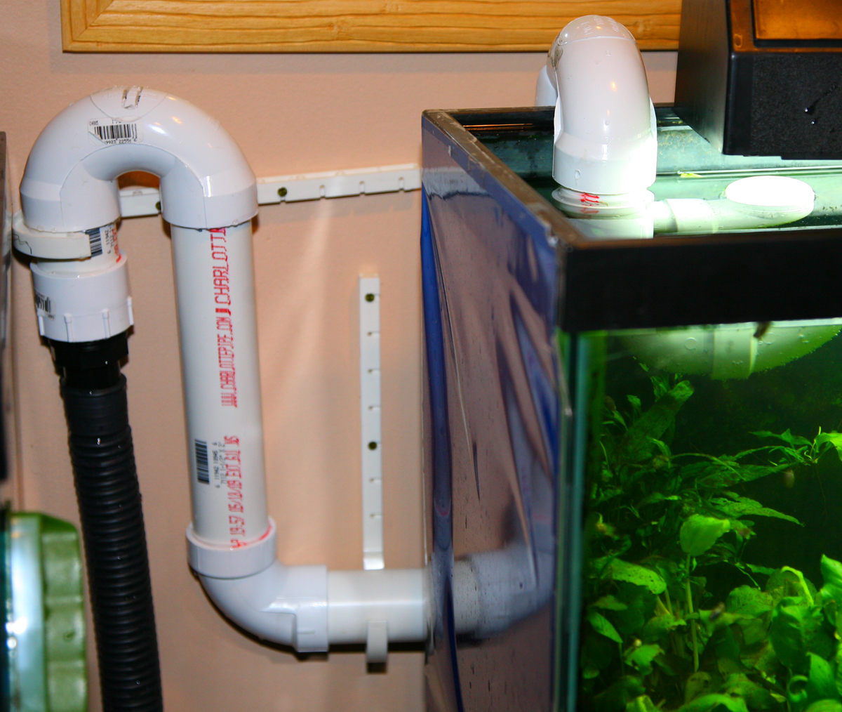
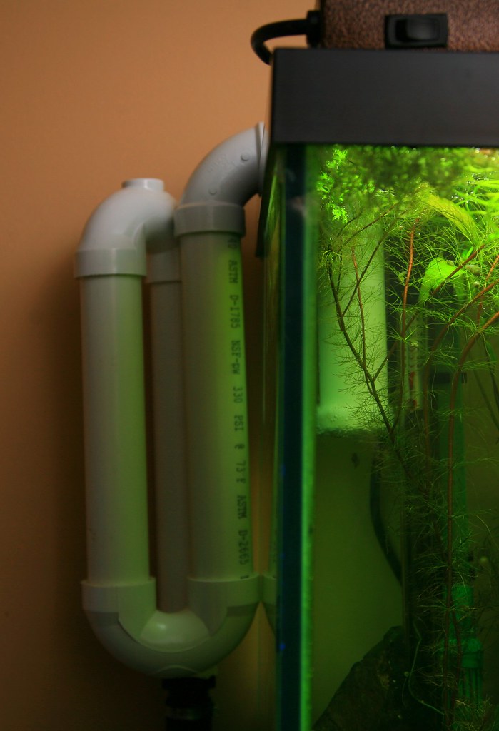
Essentially I built an overflow system out of 1.5" PVC pipe that hangs on the back of the tank, and then added a long corrugated garden drainage tube onto the PVC overflow and drilled through my sheet rock wall.
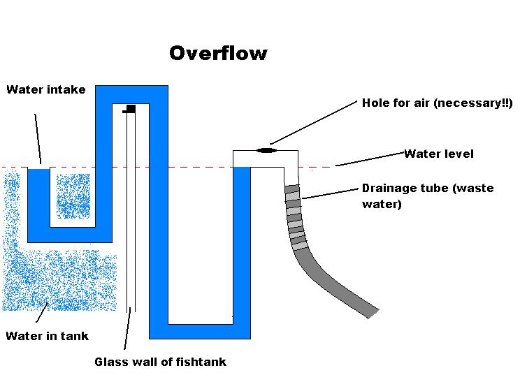
A little note on overflow systems: Overflow systems, for those that don't know, are just tubes with a U turn in them where the water permanently stays inside the U bend. What ends up happening is that if water on one side of the U bend is raised then water spills out the other end of the U bend. When the water level in the tank gets too high the excess spills over into the drainage pipe.
Overflow concept:
![Image]()
First overflow I built:
![Image]()
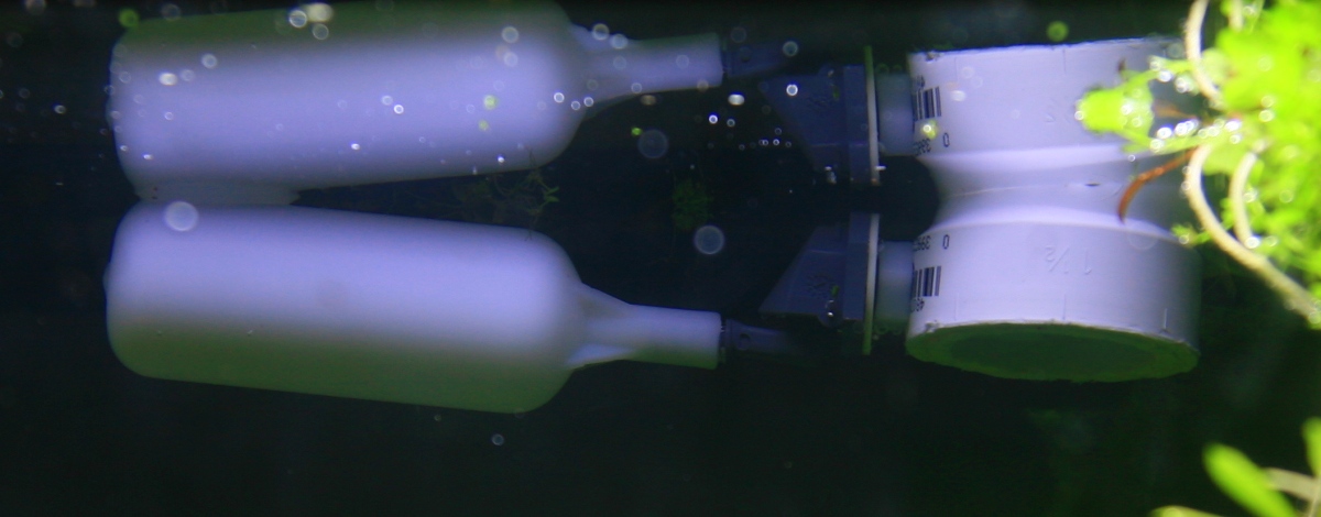
Second overflow I built:
![Image]()
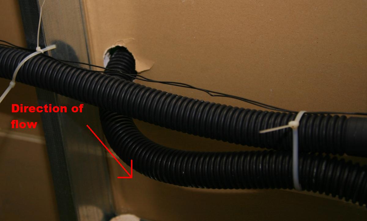
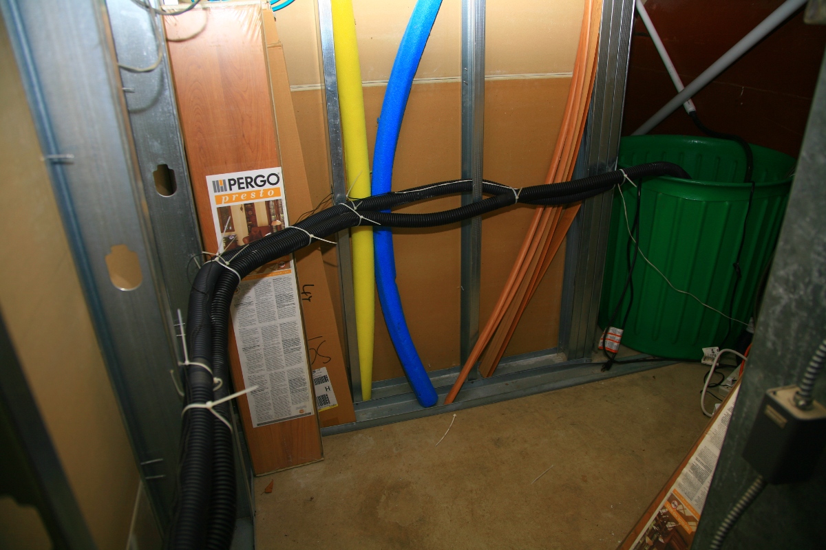
From there the drain pipe runs into a 60g plastic tub from home depot that sits in the boiler room behind my tanks (on the other side of a sheet rock wall).
Drain pipe seen from behind the sheet rock wall:
![Image]()
Drain pipe and 60g sump bucket:
![Image]()
Once the water is in the bucket it must be pumped out on a regular basis. At first I bought a 1/3 hp sump pump off ebay, but as does occasionally happen it arrived broken, incapable of pumping water. The float valve that controlled the sump did work though and so instead of connecting the sump pump to the sump float switch I connected an aquarium pump to the float valve (very easy to do, I just plugged the pump into the float valve's power cord). Now what happens is: when the water level rises and triggers the sump float switch the aquarium pump turns on and pumps the water into a PVC pipe (1" diameter) that I have running outside. I had to drill through the concrete basement wall which entailed me renting a large rotary drill from home depot for 42$. The PVC waste water pipe runs into a gutter drainage system we have outside (preexisting system).
Inside the sump:
![Image]()
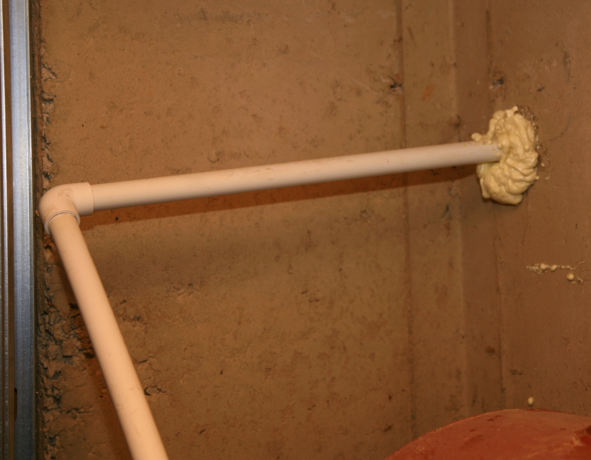
Waste water PVC pipe through concrete basement wall:
![Image]()
Fresh water source:
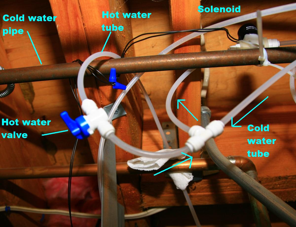
The second part of my water change system involves getting fresh water into the tank. I chose to use ice-kit maker saddle valve taps (cheaply bought from home depot) because they are very easy to install and can be adjusted to allow a few drops an hour to several dozen gallons per hour through them. I installed two saddle valve taps per fish tank on the water change system. One valve was put into the cold water pipe, the other valve in the hot water pipe. I joined the tubes with a 3-way easy connect joiner and placed another valve in the hot water line before the 3-way connect joiner so that I can precisely control the hot water going into my tank.
Saddle valves connected to house water mains:
![Image]()
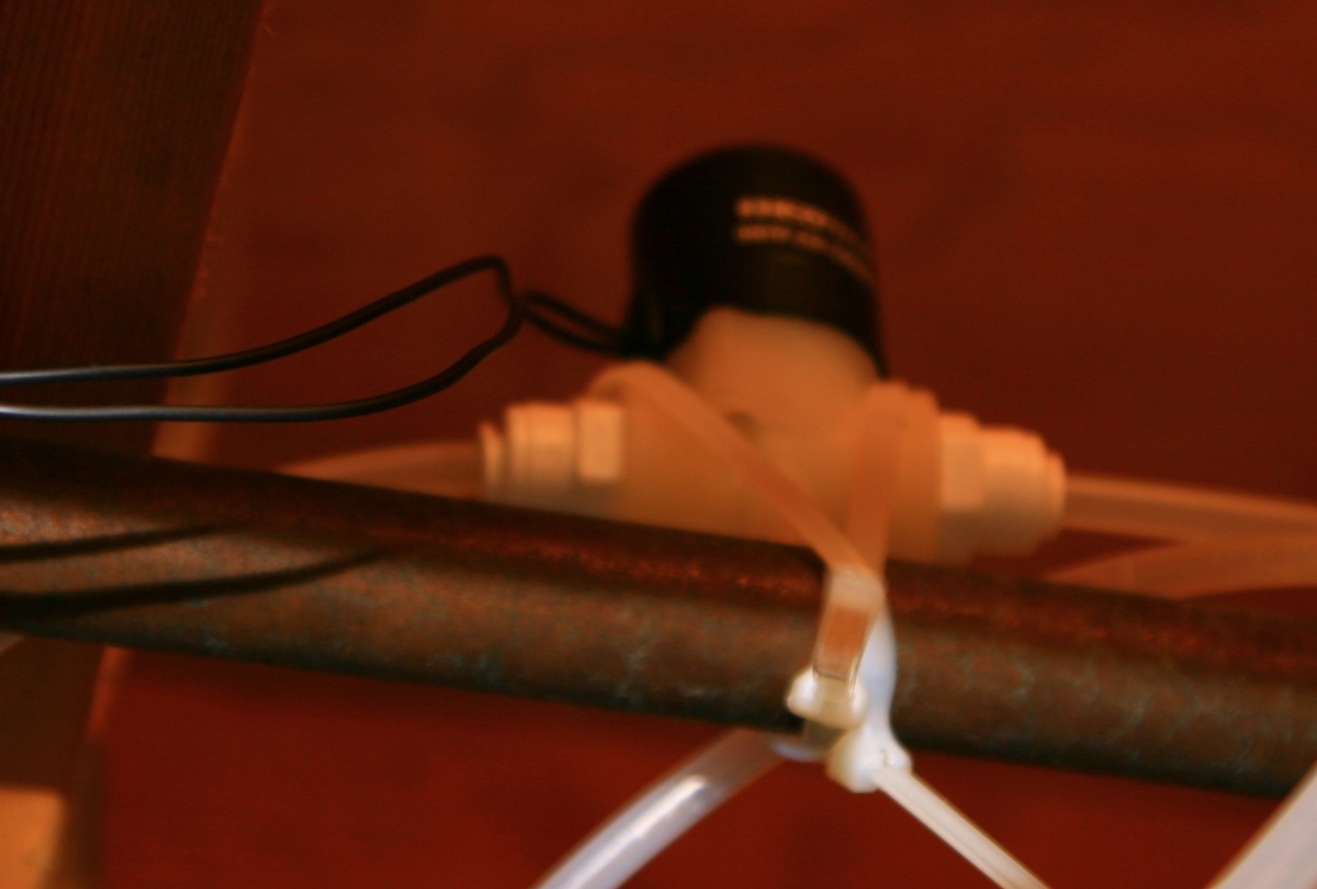
3 way connector and hot water valve:
![Image]()
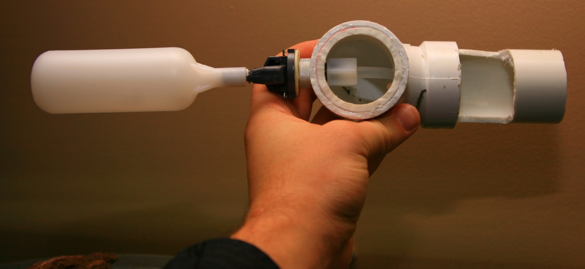
The water tube is then fed through the wall and connected to a small mount which I built on the side of my tank out of PVC pipe. The mount holds a plastic float valve. The water tube is connected to the float valve. I came up with two designs, I prefer the second one")
![Image]()
Second mount design:
![Image]()
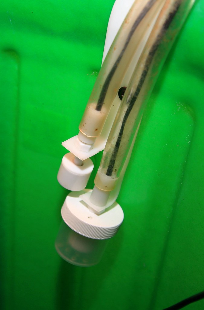
Second mount underside:
![Image]()
Second mount in tank:
![Image]()
Safety features:
The first safety feature I installed was to add a float valve to the incoming water tube. The float sits inside the fish tank and is attached with a PVC pipe mount (see above). The purpose of this float valve is just in case the overflow gets clogged for whatever reason (leaves, dead fish, etc...) the incoming water will start to rise and then push the float valve up, stopping the incoming water before the tank overflows.
The second safety feature I added was a solenoid in the incoming water tube. A solenoid for those that don't know is just a magnetically controlled valve that opens and closes depending on whether electricity is flowing through it or not. My solenoid is designed so that it is usually closed when unpowered, when power is supplied to it, it opens and allows water to pass through. The reason this solenoid is necessary is because if the sump overfills for whatever reason (pump dies, sump pump float switch gets stuck and doesn't trigger the aquarium pump, etc...) then the solenoid should be triggered to shut incoming water into the fish tank, preventing the sump from overflowing. The way the solenoid pump knows how to do this is because there are two float switches (two for redundancy and more safety) placed at the top of the sump bucket. If either of these two float switches are triggered by rising water then they send a signal to a relay (an electronic device necessary for this kind of use) that cuts the power supplied to the solenoid, thereby closing it and stopping anymore water from flowing into the fish tank and consequently preventing anymore water from entering the overflow and sump.
Solenoid in fresh water tube:
![Image]()
Float switches in sump pump:
![Image]()
The power strip and relay that controls it.
![Image]()
If you look carefully in the above picture you will see that there are two power strips. One of the power strips (left most one) is wired into the relay. Basically the relay controls the power strip itself and the float switches in the sump bucket control the relay. So what ends up happening when water rises too high is the float switches are triggered, they send a message to the relay box which cuts the power leading to the power strip and since the solenoid is plugged into the power strip, the solenoid loses power too and closes. I chose to wire a power strip to the relay because I will be adding more tanks to my water change system and therefore I need more solenoids to individually control the incoming fresh water to each tank. The beauty of this arrangement is that if the float switch is triggered in the sump the relay shuts off power to all solenoids and all incoming freshwater to all tanks is shut off. This way no tank will be able to add more water to the sump. In addition, each tank functions individually from the other due to the float valves mounted on each tank. If one tank's overflow gets clogged then only that tank will shut off the incoming freshwater. Each tank functions separately, but is united.
Relay assembly instructions (this is how I wired my relay and power socket) http://www.aquahub.com/store/media/TopitOffKitPremiumInstruxCompDec07.pdf
This is essentially how I have my relay, power strip and float switches set up, just instead of inside a tank it is all inside my sump:
Relay setup:
![Image]()
Approximate Costs for adding 1 tank to a water change system
Overflow system
10 feet of PVC tubing at 1.5" diameter for overflow and tank mount - $3 -- from home depot
3 U bend PVC joiners - $8 -- from home depot
PVC cement - $3 -- from home depot
1 90 degree PVC bend - $0.70 -- from home depot
1 PVC 1.5" joiner with female screw (used for attaching a bard for the waste water pipe) $1.50
1 black corrugated 20 foot waste water drain pipe - $9 -- from home depot
1 pack of 12 zipties for securing waste pipe - $1.50 -- from home depot
1 garden 60 gallon sump bucket - $39 -- from home depot
1 aquarium pump - $30 -- from ebay
1 sump float switch - ??? -- from ebay
1 basement hole in the wall - $42 -- rented drill from home depot
Total: $137.70 + ??? (sump float switch) (includes tax and shipping)
Fresh water
20 feet of polyethyline tubing (1/4") -- $3 from home depot
2 saddle valves - $14 -- from home depot
1 three way quick connect tube joiner - $3 -- from home depot
1 valve for hot water - $7 -- from home depot
Total: $27 (includes tax)
Safety features
1 Relay kit with float switches - $46 -- from aquahub.com http://www.aquahub.com/store/product26.html
1 float valve for in tank - $14 -- from ebay
1 reel of electrical wire (for solenoid) for 90 feet - $8 -- from radioshack
1 power strip - $8 -- from home depot
1 solenoid valve - $21 -- from ebay
2 plastic fittings for the solenoid valve - $3 -- from home depot
Total: $ 100 (includes tax)
Grand total: $264.70
Not a bad price in my opinion for never having to do another water change ever considering lights can cost about this much for larger tanks, and CO2 systems come close.
I have plans of adding flood detectors that sound an alarm so I know if a tank is overflowing, but I'll leave that for a later post.

My water change setup is relatively easy to make. The basic design involves three parts: an overflow, a fresh water source, and safety features to prevent overflowing. This water change system is continuous (meaning it runs 24 hours a day at a very slow rate). I have well water with no chlorine, or added softening salts. My tanks are conveniently placed in the basement where this water change system is set up.
Overflow System:
Essentially I built an overflow system out of 1.5" PVC pipe that hangs on the back of the tank, and then added a long corrugated garden drainage tube onto the PVC overflow and drilled through my sheet rock wall.
A little note on overflow systems: Overflow systems, for those that don't know, are just tubes with a U turn in them where the water permanently stays inside the U bend. What ends up happening is that if water on one side of the U bend is raised then water spills out the other end of the U bend. When the water level in the tank gets too high the excess spills over into the drainage pipe.
Overflow concept:
First overflow I built:
Second overflow I built:
From there the drain pipe runs into a 60g plastic tub from home depot that sits in the boiler room behind my tanks (on the other side of a sheet rock wall).
Drain pipe seen from behind the sheet rock wall:
Drain pipe and 60g sump bucket:
Once the water is in the bucket it must be pumped out on a regular basis. At first I bought a 1/3 hp sump pump off ebay, but as does occasionally happen it arrived broken, incapable of pumping water. The float valve that controlled the sump did work though and so instead of connecting the sump pump to the sump float switch I connected an aquarium pump to the float valve (very easy to do, I just plugged the pump into the float valve's power cord). Now what happens is: when the water level rises and triggers the sump float switch the aquarium pump turns on and pumps the water into a PVC pipe (1" diameter) that I have running outside. I had to drill through the concrete basement wall which entailed me renting a large rotary drill from home depot for 42$. The PVC waste water pipe runs into a gutter drainage system we have outside (preexisting system).
Inside the sump:

Waste water PVC pipe through concrete basement wall:
Fresh water source:
The second part of my water change system involves getting fresh water into the tank. I chose to use ice-kit maker saddle valve taps (cheaply bought from home depot) because they are very easy to install and can be adjusted to allow a few drops an hour to several dozen gallons per hour through them. I installed two saddle valve taps per fish tank on the water change system. One valve was put into the cold water pipe, the other valve in the hot water pipe. I joined the tubes with a 3-way easy connect joiner and placed another valve in the hot water line before the 3-way connect joiner so that I can precisely control the hot water going into my tank.
Saddle valves connected to house water mains:

3 way connector and hot water valve:
The water tube is then fed through the wall and connected to a small mount which I built on the side of my tank out of PVC pipe. The mount holds a plastic float valve. The water tube is connected to the float valve. I came up with two designs, I prefer the second one

Second mount design:

Second mount underside:
Second mount in tank:
Safety features:
The first safety feature I installed was to add a float valve to the incoming water tube. The float sits inside the fish tank and is attached with a PVC pipe mount (see above). The purpose of this float valve is just in case the overflow gets clogged for whatever reason (leaves, dead fish, etc...) the incoming water will start to rise and then push the float valve up, stopping the incoming water before the tank overflows.
The second safety feature I added was a solenoid in the incoming water tube. A solenoid for those that don't know is just a magnetically controlled valve that opens and closes depending on whether electricity is flowing through it or not. My solenoid is designed so that it is usually closed when unpowered, when power is supplied to it, it opens and allows water to pass through. The reason this solenoid is necessary is because if the sump overfills for whatever reason (pump dies, sump pump float switch gets stuck and doesn't trigger the aquarium pump, etc...) then the solenoid should be triggered to shut incoming water into the fish tank, preventing the sump from overflowing. The way the solenoid pump knows how to do this is because there are two float switches (two for redundancy and more safety) placed at the top of the sump bucket. If either of these two float switches are triggered by rising water then they send a signal to a relay (an electronic device necessary for this kind of use) that cuts the power supplied to the solenoid, thereby closing it and stopping anymore water from flowing into the fish tank and consequently preventing anymore water from entering the overflow and sump.
Solenoid in fresh water tube:
Float switches in sump pump:
The power strip and relay that controls it.

If you look carefully in the above picture you will see that there are two power strips. One of the power strips (left most one) is wired into the relay. Basically the relay controls the power strip itself and the float switches in the sump bucket control the relay. So what ends up happening when water rises too high is the float switches are triggered, they send a message to the relay box which cuts the power leading to the power strip and since the solenoid is plugged into the power strip, the solenoid loses power too and closes. I chose to wire a power strip to the relay because I will be adding more tanks to my water change system and therefore I need more solenoids to individually control the incoming fresh water to each tank. The beauty of this arrangement is that if the float switch is triggered in the sump the relay shuts off power to all solenoids and all incoming freshwater to all tanks is shut off. This way no tank will be able to add more water to the sump. In addition, each tank functions individually from the other due to the float valves mounted on each tank. If one tank's overflow gets clogged then only that tank will shut off the incoming freshwater. Each tank functions separately, but is united.
Relay assembly instructions (this is how I wired my relay and power socket) http://www.aquahub.com/store/media/TopitOffKitPremiumInstruxCompDec07.pdf
This is essentially how I have my relay, power strip and float switches set up, just instead of inside a tank it is all inside my sump:
Relay setup:

Approximate Costs for adding 1 tank to a water change system
Overflow system
10 feet of PVC tubing at 1.5" diameter for overflow and tank mount - $3 -- from home depot
3 U bend PVC joiners - $8 -- from home depot
PVC cement - $3 -- from home depot
1 90 degree PVC bend - $0.70 -- from home depot
1 PVC 1.5" joiner with female screw (used for attaching a bard for the waste water pipe) $1.50
1 black corrugated 20 foot waste water drain pipe - $9 -- from home depot
1 pack of 12 zipties for securing waste pipe - $1.50 -- from home depot
1 garden 60 gallon sump bucket - $39 -- from home depot
1 aquarium pump - $30 -- from ebay
1 sump float switch - ??? -- from ebay
1 basement hole in the wall - $42 -- rented drill from home depot
Total: $137.70 + ??? (sump float switch) (includes tax and shipping)
Fresh water
20 feet of polyethyline tubing (1/4") -- $3 from home depot
2 saddle valves - $14 -- from home depot
1 three way quick connect tube joiner - $3 -- from home depot
1 valve for hot water - $7 -- from home depot
Total: $27 (includes tax)
Safety features
1 Relay kit with float switches - $46 -- from aquahub.com http://www.aquahub.com/store/product26.html
1 float valve for in tank - $14 -- from ebay
1 reel of electrical wire (for solenoid) for 90 feet - $8 -- from radioshack
1 power strip - $8 -- from home depot
1 solenoid valve - $21 -- from ebay
2 plastic fittings for the solenoid valve - $3 -- from home depot
Total: $ 100 (includes tax)
Grand total: $264.70
Not a bad price in my opinion for never having to do another water change ever considering lights can cost about this much for larger tanks, and CO2 systems come close.
I have plans of adding flood detectors that sound an alarm so I know if a tank is overflowing, but I'll leave that for a later post.